
Structure and Principle of ABB VD4 Circuit Breaker Operating Mechanism
Jun 20,2023 | simplybuy industrial
VD4 switch is ABB's classic medium-voltage circuit breaker product, with a global sales volume of nearly one million units. Generally speaking, the reliability of the VD4 switch is very high, but various faults still inevitably occur, especially in the part of the operating mechanism. During the repair process, maintenance personnel can only understand the structure and principle of the mechanism through the product manual provided by ABB. Most of the reference books on the circuit breaker operating mechanism on the market directly quote the content of the product manual, because it is not detailed enough to Instruct the maintenance personnel to complete the work, causing a lot of inconveniences. The author recently had the honor of dismantling a scrapped VD4 switch, dismantling and sorting out its internal structure, and adding some personal understanding at the same time, hoping to help the maintenance personnel in their actual work.
The basic structure of the VD4 operating mechanism is composed of a planar scroll spring and a main shaft. The maintenance and conversion between the opening and closing positions are realized by a multi-stage tripping mechanism, and the output is output through the cam lever structure.
1. Energy storage module
VD4 uses planar scroll springs as energy storage elements. Compared with linear tension springs or compression springs used by most spring mechanisms, its output characteristics are more stable and more consistent with the action characteristics of the mechanism, thus greatly improving the overall efficiency of the operating mechanism.

Figure 1 Plane scroll spring
One end of the plane scroll spring is fixed on the main shaft, and the other end is fixed on the spring casing, as shown in Figure 1. When storing energy, the main shaft end of the volute spring is fixed, and the energy storage motor or the energy storage rocker drives the spring casing to rotate clockwise (viewed from the left side of the mechanism, the same below) through the ratchet pawl, chain, and large gear to tighten the volute. Roll spring. When opening and closing, the shell end of the scroll spring is fixed, the tripping mechanism is released, the main shaft rotates clockwise under the drive of the scroll spring, and the energy of the scroll spring is output.
Since the VD4 uses a planar scroll spring, the switching mode of the spring "uncharged" and "stored" is also different from most spring operating mechanisms. It is fixed on the scroll spring shell with a gap The cooperation between the disk, the auxiliary cam fixed on the main shaft, and the roller installed on the energy storage connecting rod is realized. To put it simply, after the energy storage is completed, the roller is driven into the notch of the disk by the energy storage connecting rod, and the energy storage connecting rod rotates at a certain angle, and the energy storage auxiliary contact linked with it and the energy storage mechanical indicator switch to "already Energy storage” state; during the closing process of the circuit breaker, the maximum radius of the auxiliary cam turns over the gap of the disc, pushes the roller back to the outer edge of the disc, drives the energy storage connecting rod to return to the original angle, and the energy storage auxiliary contact and energy storage mechanical indication Return to the "non-energy storage" state.
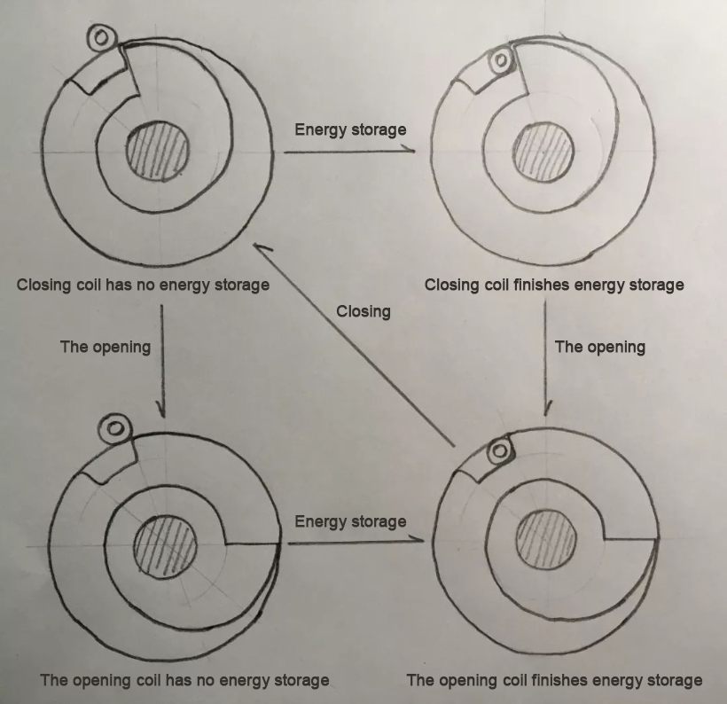
Figure 2 Schematic diagram of energy storage state transition
What needs to be pointed out here is that for a traditional VD4 switch in the state of opening without energy storage, considerable energy is still stored in the planar scroll spring. Still have to pay attention to safety.
2. Trip module
The trip module of the VD4 switch operating mechanism is quite aesthetically designed and unique. Seemingly complicated, dismantling and analyzing it, the entire tripping module can be decomposed into three basic tripping structures:
The first-stage tripping structure is composed of the front roller and the brake disc of the large fan-shaped plate, which is equivalent to a special-shaped "detent+roller" tripping structure; the second stage is composed of the large fan-shaped plate and the big half shaft, which is A typical "half shaft + fan-shaped plate" tripping structure; the third stage is composed of the opening half shaft, the opening fan-shaped plate, the closing half-shaft, and the closing fan-shaped plate, which are two sets of "half shaft + fan-shaped plate" tripping Clamp combination of structures.

Figure 3 Structural diagram of the trip module
Let’s first look at the holding function of the trip module. Take the closing position as an example. After the closing action is completed, the front roller of the large fan-shaped plate just falls into the slot corresponding to the closing position on the brake disc. At this time, the large half shaft is kept in place under the action of the pincer structure formed by the opening and closing sector plates, which prevents the front rollers of the large sector plates from being lifted, and the front rollers lock the brake disc to keep the main shaft at the closing position. Location.
Looking at its tripping function again, take the opening acts as an example from the previous article. After the mechanism receives the opening command, the opening semi-axis turns clockwise through a certain angle, and the opening fan plate loses the temporary fulcrum and rotates clockwise. The pincer-shaped support structure composed of the opening and closing fan-shaped plates is disintegrated, and the large semi-axis rotates counterclockwise under the action of the return spring to release the large fan-shaped plate. The large fan-shaped plate lifts the front roller under the action of the return spring to release the brake disc. Turn clockwise under the action of the scroll spring to start the opening action.
During the opening process, the connecting rod on the auxiliary shaft of the opening and closing position (as shown in Figure 4) pushes the opening sector plate to reset, and buckles it on the opening semi-shaft again, so that the clamp-shaped support structure formed by the opening and closing sector plates Re-establish and push the big half shaft back to the original angle; at the same time, the auxiliary discs on both sides of the brake disc act on the rear rollers of the large fan-shaped plate when they rotate with the main shaft so that the rear part of the large fan-shaped plate is lifted and the front part is lowered. Press it to prepare for the next locking of the front roller to the brake disc.

Figure 4 Opening and closing position auxiliary shaft connecting rod
3. Output module
The output module of the VD4 operating mechanism consists of three cam discs on the main shaft and three double-arm moving links at the bottom of the mechanism. The double-arm moving link is equivalent to a lever, the fulcrum is in the middle, the front end is affected by the main shaft cam plate, and the rear end is connected to the insulating pull rod of the vacuum bubble and the opening spring.
When the switch is closed, the cam disc rotates with the main shaft and presses down the rollers at the front end of the double-arm movable connecting rod along the curve of its outer edge, so that the rear end of the connecting rod is lifted, and the insulating pull rod is pushed upward, so that the dynamic and static contacts in the vacuum bubble are closed, realizing close. At the same time, the opening spring is compressed to store energy for the opening act.
When the gate is opened, the cam disc rotates with the main shaft and releases the rollers at the front end of the double-arm movable connecting rod along the curve of its outer edge. The dynamic and static contacts are separated to realize an opening.
4. Locking function
Compared with other types of circuit breakers, the setting of the VD4 locking function is very comprehensive, which provides a reference template for the acceptance of the "five defenses" of handcart circuit breakers. Let’s introduce them one by one:
1. When the handcart is in the middle position, the circuit breaker is prohibited from closing:
Measure a: Set up the closing locking electromagnet Y1, that is, connect the limit switches S8 and S9 in parallel with the closing locking electromagnet Y1 to form the closing locking circuit. Only when the handcart of the circuit breaker is in the test position or working position, S8 or S9 is connected to the closing locking circuit, the closing locking electromagnet Y1 is charged, and the moving iron core is attracted to release the mechanical locking of the closing semi-axis; at the same time, it is connected in series The auxiliary switch S2 in the closing circuit of the circuit breaker is linked with the moving iron core of the closing locking electromagnet Y1, which makes the circuit ready for executing the closing command. As mentioned above, the measure combines mechanical locking and electrical locking, which is a comprehensive locking scheme.
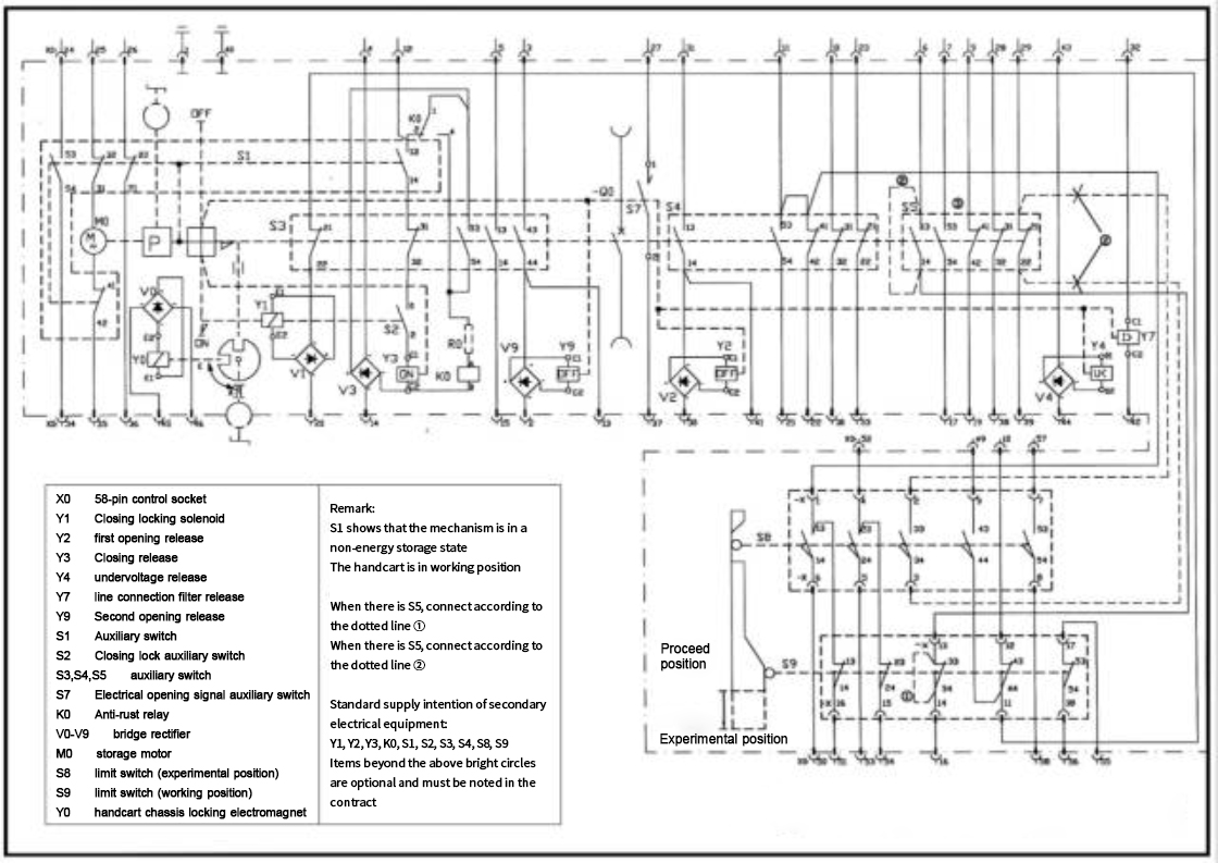
Figure 5 Handcart type VD4 electrical control wiring diagram
Regarding the necessity of setting the auxiliary switch S2 in the closing circuit, here is an explanation: First of all, setting S2 is to increase the electrical locking on the basis of the mechanical locking function of the closing locking electromagnet Y1, which undoubtedly increases the reliability of the locking function. But the role of S2 is far more than that. Assuming that the auxiliary switch S2 is not set in the closing circuit if the circuit breaker handcart receives an electrical closing command when the handcart is in the middle position, the closing circuit will be connected at this time, and the closing lock electromagnetic Under the blocking action of iron Y1, the closing semi-axis cannot rotate, the switch cannot be closed, and the auxiliary switch of the circuit breaker cannot be displaced. This will cause the closing electromagnet to be energized for a long time, and it will be overheated and burned. Therefore, connecting the auxiliary switch S2 in series in the closing circuit of the circuit breaker is not a icing on the cake, but necessary.
Measure b: Set the closing interlock mechanism, as shown in Figure 6. The interlock mechanism is established between the lead screw of the chassis car and the closing half shaft of the circuit breaker through the four-link structure composed of the circuit breaker interlock plate (as shown in Figure 7), the interlock lever and the locking lever in the chassis. Purely a mechanical locking relationship.
When the handcart of the circuit breaker is in the test position or the working position, the circuit breaker interlock plate in the chassis is in a horizontal position under the action of the return spring. At this time, the positions of the interlock lever and the locking lever are shown in Figure 6. The locking lever There is a gap between the top and the plastic cam of the closing half shaft, and the closing half shaft can rotate freely; when the circuit breaker handcart is in the middle position, the circuit breaker interlocking plate in the chassis car is close to the wire screw under the action of the lead screw. One side of the lever is lifted, and the locking lever acts on the locking lever through the interlocking lever, so that the top end is just stuck under the plastic cam of the closing half shaft, and the rotation of the closing half shaft is locked.

Figure 6 Closing Interlock Mechanism

Figure 7 VD4 handcart chassis components
During the study, it was found that many operating units had not released the mechanical lock normally due to the deformation or jamming of the chassis of the handcart, and then burned the closing coil. In actual work, the inspection and maintenance of related components should be strengthened.
2. When the circuit breaker is closed, the handcart is prohibited from shaking in/out:
The VD4 switch uses the cooperation between the locking frame fixed on the interlocking plate in the closing interlocking mechanism and the front rollers of the B-phase dual-arm moving link in the operating mechanism to realize the blocking of the entry and exit of the handcart when the circuit breaker is closed.
When the handcart is in the test position or the working position, after the circuit breaker is closed, the front rollers of the two-arm moving link are pressed down, and there is only a small gap with the locking frame on the interlocking plate. At this time, if you use the crank to shake the lead screw to enter and exit the handcart, the lead screw will push the circuit breaker interlock plate in the chassis to lift up, and the circuit breaker interlock plate will press against the roller at the front end of the double arm link through the locking frame after a slight movement. , it reacts on the lead screw, so that the lead screw cannot rotate, and the rocking in and out of the handcart is blocked. Obviously, this is a purely mechanical locking method.
3. When the circuit breaker does not store energy, it is forbidden to close the switch:
This blocking function does not belong to the "five defenses" requirements, but it is very important for the circuit breaker itself. When the circuit breaker is closed without energy storage or energy storage is not completed, the closing speed will inevitably decrease, and the closing force will also decrease. If the closing time is too long or the closing force is not enough to overcome the electric repulsion, it will lead to closing failure. Very serious consequences.
The VD4 switch uses the cooperation between the energy storage locking plate on the energy storage connecting rod (mentioned above) and the extension plate of the closing sector plate to realize the closing lock in the state of no energy storage.
When the circuit breaker is not storing energy or in the process of energy storage, the roller on the energy storage connecting rod leans against the outer edge of the disc with a notch. On the extension plate, the closing fan-shaped plate is rotated through a small angle, and the closing half shaft is disengaged, that is, the temporary fulcrum formed by the contact of the closing half shaft and the closing fan-shaped plate in the third-stage pincer tripping structure is transferred to the energy storage On the contact point of the locking plate and the extension plate of the closing fan-shaped plate, the tripping function of the closing half shaft has been removed, and the closing function has also been blocked.
After the energy storage of the circuit breaker is completed, the roller on the energy storage connecting rod is buckled in the gap of the disc. At this time, the angle of the energy storage connecting rod makes the energy storage locking plate be located There is no contact between the fan-shaped plates, so the tripping function of the closing half shaft will not be affected, and the gate can be closed normally.

Figure 8 a Energy storage lock plate position when energy is stored

Figure 8 b The position of the energy storage lockout plate when no energy is stored
In order to cooperate with the above mechanical locking method, the VD4 switch is also connected in series with the energy storage auxiliary switch S1 (as shown in Figure 5) in the closing circuit, which increases the electrical locking function and prevents the burning of the closing electromagnet.
Comment


